RR SIGNAL PIX . COM
Welcome to RR SIGNAL PIX . COM
Best Viewed at 1280 x 800 Res.

jQuery Superfish dropdown menu example with full touch support for Android, iOS and Windows 8.


Gresham Tower
Chicago, Illinois

Gresham Tower was built by The Rock Island Railroad in 1953, the new tower replaced an all-electric interlocking that was installed in 1906. The new tower was of a brick and concrete construction, all existing relays and wiring was removed. The new tower contained a interlocking machine that was quite unique, this machine being made by Standard Telephones and Cable Limited of London, England. The interlocking machine used a series of sequence switches to clear routes. These sequence switches where commonly used in telephone switching equipment. This type of interlocking machine was only used a few times, this being the only one ever constructed and used in North America. Standard Telephones and Cable Limited only constructed four other interlocking machines, two were the 1949 model and another two were the improved model; all in which were used in Europe. The plant had a total of 13 single switches, 9 crossovers, 3 movable-point frogs, 14 derails, and 41 home signals. Of the 41 home signals 19 were high signals and the other 22 were dwarf signals. The interlocking was a "Route Lever Interlocking" and worked on the same principal of the eNtrance and eXit (NX) interlocking. For each home signal there were a number of routes that could be chosen, that corresponds to a exit signal. The control panel was 6 foot high and 12 feet long, and at an angle. The panel contained all the route selection keys and had the interlocking diagram on the back. Extra room was added to the right side of the panel for future expansion of the interlocking plant, though the plant was never expanded. Over the years the plant was modified to remove tracks and switches, the model board was also modified by addition of tape to cover the removed tracks. This interlocking survived until January 30th, 2010 when Metra closed the tower and remoted the interlocking controls to a main dispatching center. The interlocking machine was powered down and removed from service. Since then all the common interlocking relays have been removed and kept in stock as spares. The panel still remains in the top floor of the tower, all the sequence switches still remain in the cabinets downstairs. The tower is currently occupied by the Metra signal department and used as the offices for that area. It is not known what will happen to the interlocking machine.


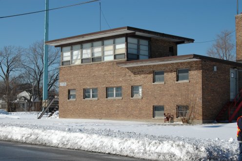
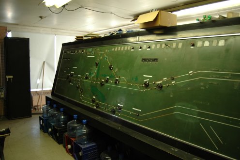
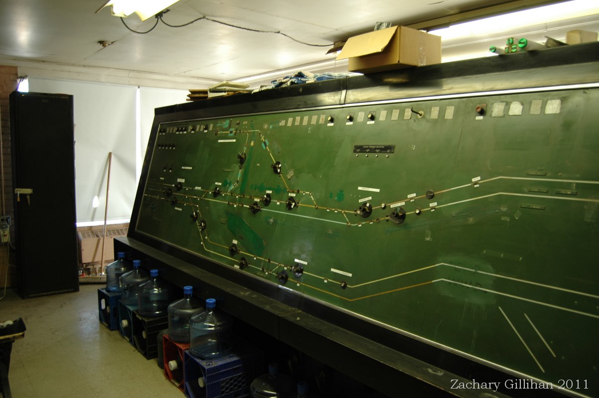
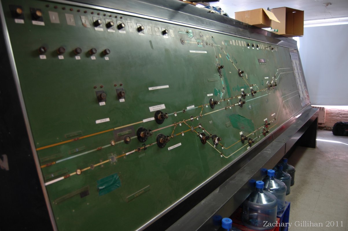
Left: First Floor, Interlocking Machine
Right: Second Floor, Panel

SYSTEM OPERATION:
The Interlocking Sequence Switches are designed to provide the necessary interlocking between conflicting routes in the Gresham Plant. The manner in which this interlocking is obtained is briefly as follows:

A number of routes, or partial routes, which interlock with each other, are controlled from a corresponding number of positions on one sequence switch, so that, if a sequence switch is driven to one route position, this one route, and no other, can be set, since a sequence switch rotor can obviously only be in one of its 12 positions at any one time. This plant's 41 home signals could be cleared for a total of 32 track circuit controlled routes, and another 117 non-track circuit routes could be cleared by using the Call-On. A total of 25 Sequence Switches where required to provide all the necessary interlocking and control of the plant.
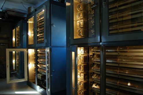
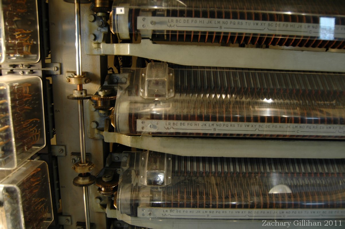
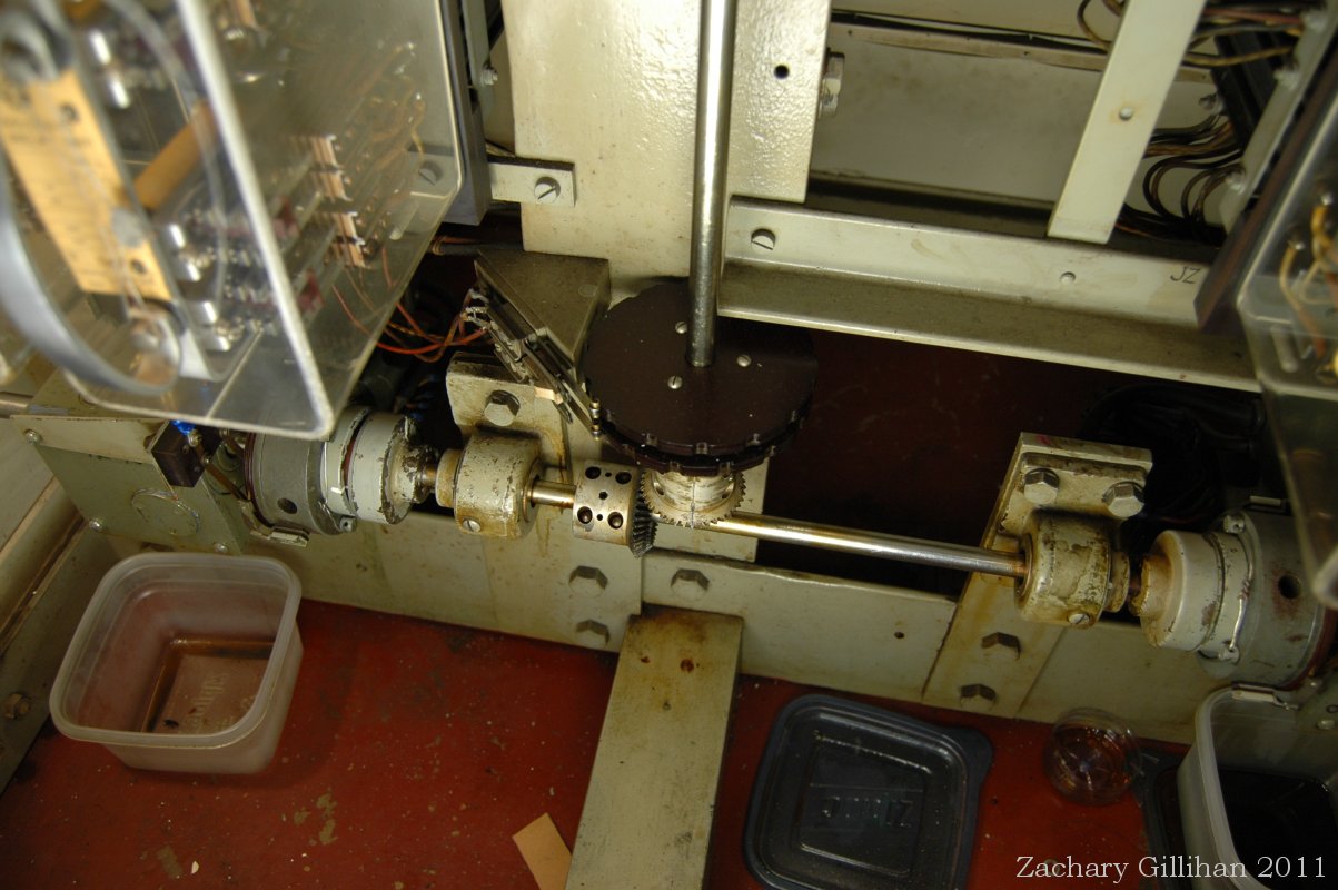
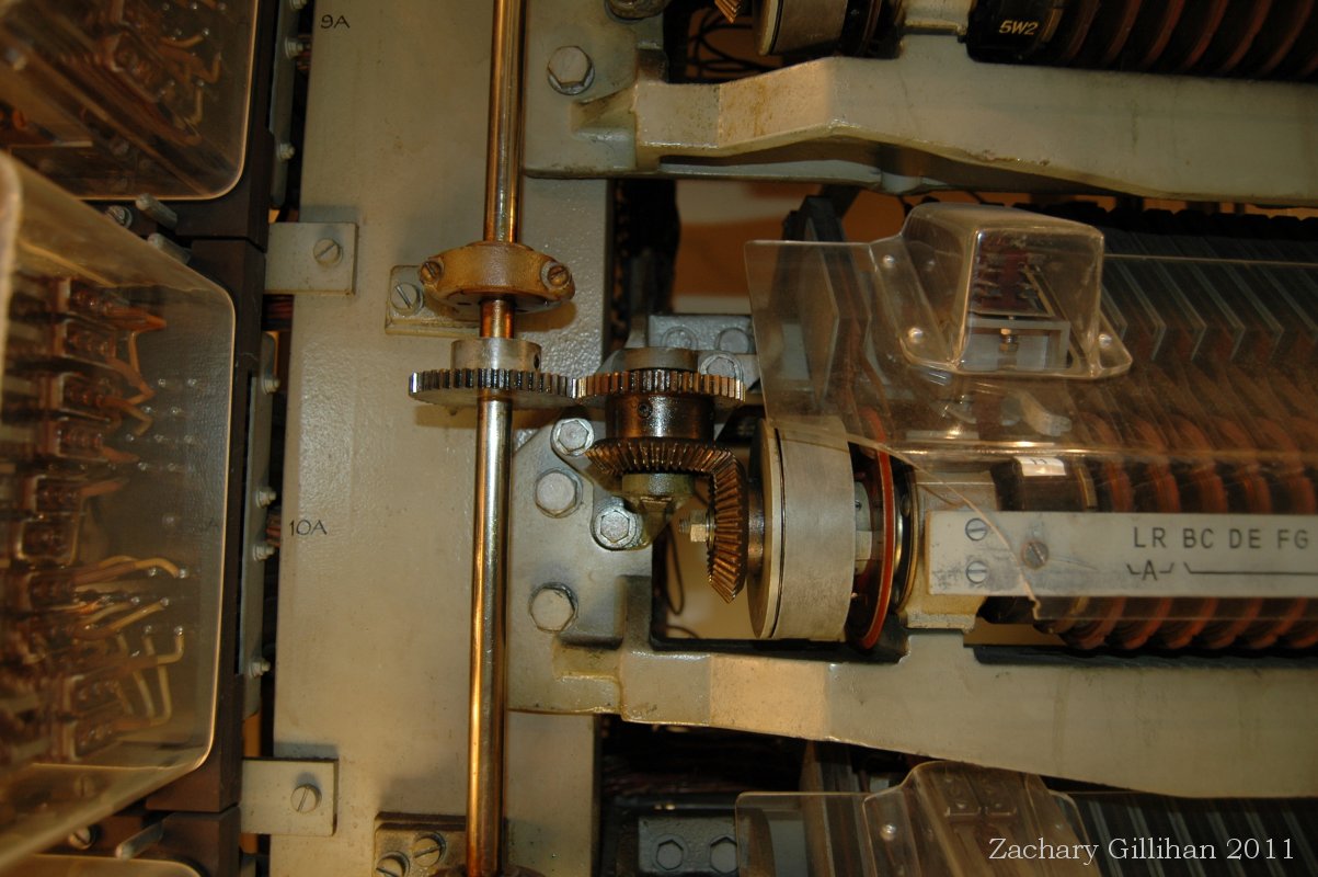
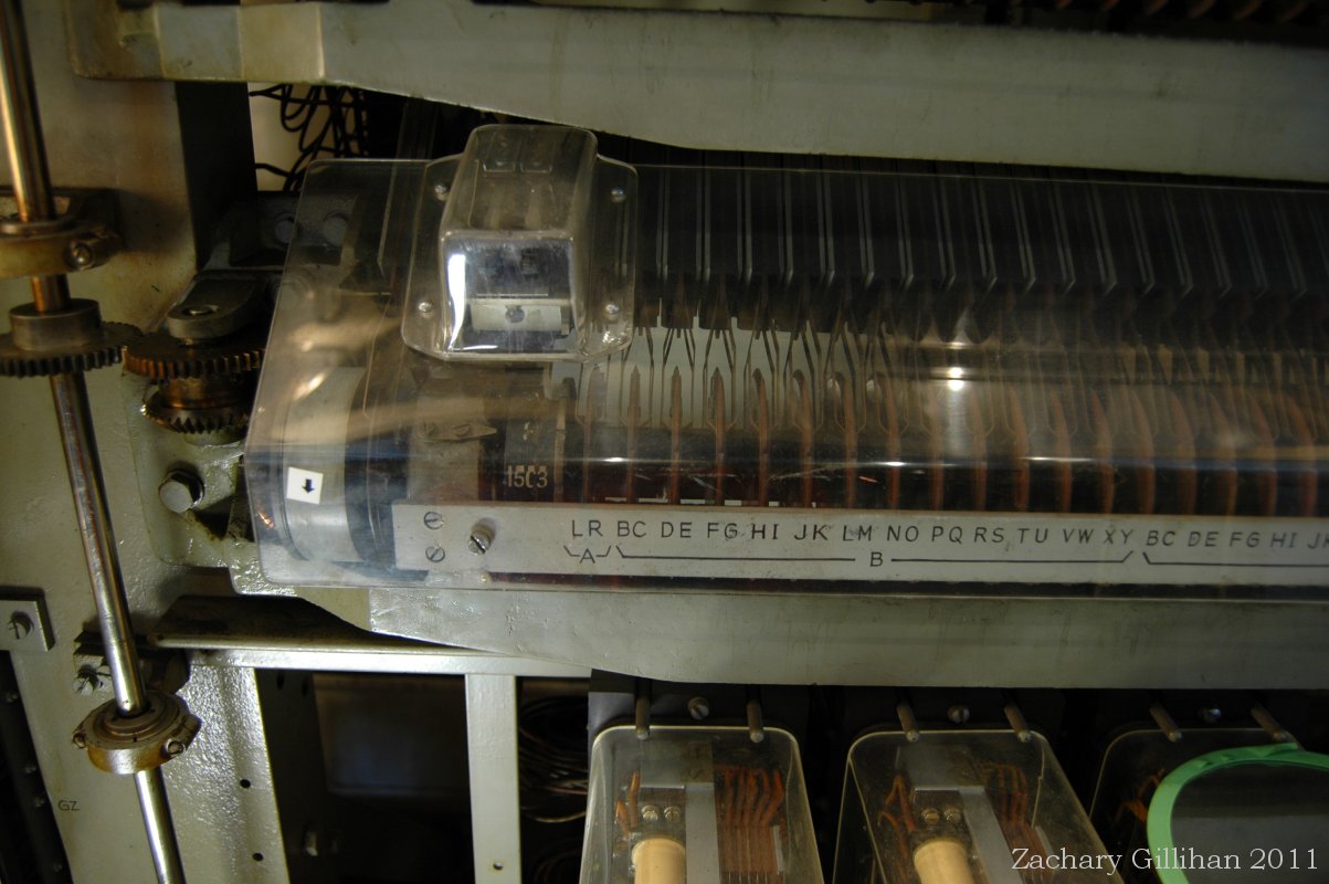
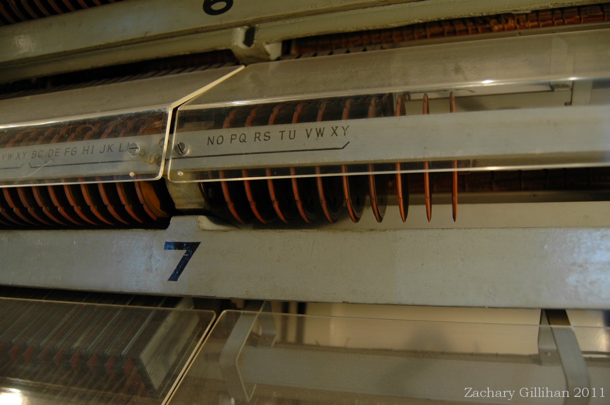
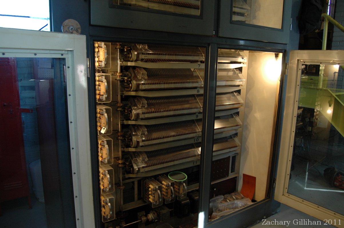
Left: Cabinet of Sequence Switches.
Right: Close-up view of Sequence Switch
It is not possible, however, to obtain all the necessary interlocking by this mechanical method, since occasions frequently arise when, for example, two routes A and B, which do not interlock with each other, both interlock with a third route - C. It will be clear, therefore, that routes A. and B cannot be carried on the same sequence switch, since they may require to be set up simultaneously, while route C may be controlled from the same sequence switch as either A or B. If route C is controlled by the same sequence switch as route A, then electrical interlocking between the two switches will be necessary to provide the interlocking between routes B and C. This circuit interlocking, however, requires no relays, and is obtained by connections between contacting cams on the various sequence switches.

When a route through the Plant is divided for release purposes into a number of partial routes, then these partial routes are each on a different sequence switch, so that the setting up of a route is obtained by the various sequence switches running to their route or partial route positions in succession. The signal can be cleared only when all the relevant sequence switches have been proved in the correct route or partial route positions. This method of operation has been provided so that, as a train passes through the route, and each partial becomes released in turn, the sequence switches carrying such partials can be returned to the Home position, permitting the setting of new routes without waiting for the whole of the original route to be cleared.

The route selection switches on the Control Panel permit the Towerman to select the particular route which he requires to be established, and convey his intentions to the Interlocking Equipment. These route selection switches are of the multi-position rotary type, and each one may carry up to 12 routes which start from one signal. The route selection keys routes are marked by white numbers on the faceplate around the key. Call-On routes are marked by a white circle around a number.
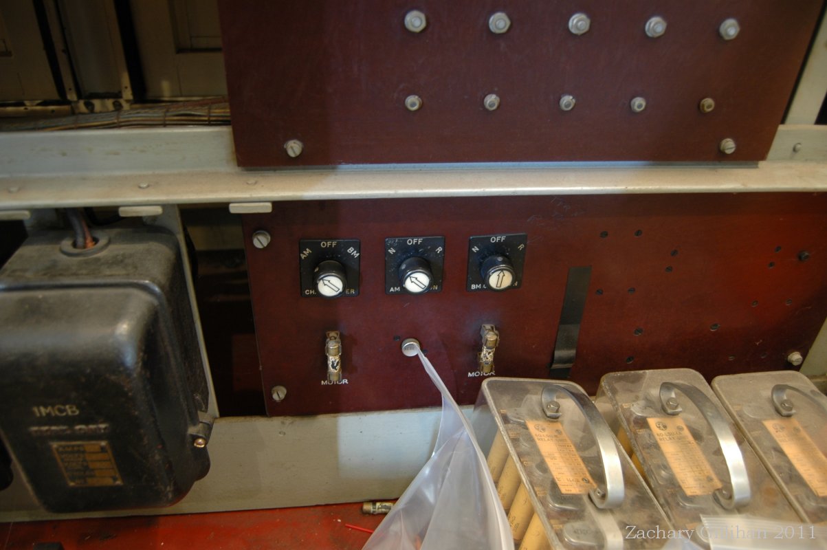
Both: Route Selection Keys
In order to understand the general operation of the System, assume that the Towerman wishes to set up a route from a signal to a particular destination, and assume that this route comprises two sections. The Towerman will turn the appropriate Route Selection Key to the desired route, and then plunge the knob. If no conflicting route has been set up, then the relevant sequence switches carrying the Route and the Partial Route, will drive in succession to the route and partial route positions. In these positions various wiper contacts on each sequence switch will be closed or opened in accordance with the interlocking conditions pertaining to those routes, certain of these cam contacts being closed ready to provide the necessary feeds to switch point and signal control circuits. Before these contacts are used, however, sequence switch auxiliary relays prove that the route positions taken up by the sequence switches agree with the route set by the Towerman on his Route Selection Key; that the sequence switches have been truly centered and locked in these route positions, and that no other sequence switch occupies a conflicting route position. Each Sequence Switch has several auxiliary relays, one being a relay that controls the operation of the motor that drives the sequence switch to the position called for. Another relay controls the operation of the motor to return the Sequence Switch to the Home position. A third relay is provided as the "proving" relay, this relay when in the correct position picks up and makes the route complete, if anything changes to the route this relay will drop out returning all the signals to red. When these conditions have been satisfied, proving relays operate, and the necessary feeds are established to switch point control relays, and after switch point detection and track circuit detection have been proved, the signal control relay will operate. When the route is cleared a Green indicator lamp next to the route selection key will light, once the train has passed or the towerman cancel's the route a red indicator will light and the green indicator will go off. This tells the towerman that the route has either been cleared, or cancelled, or the train has passed the home signal.
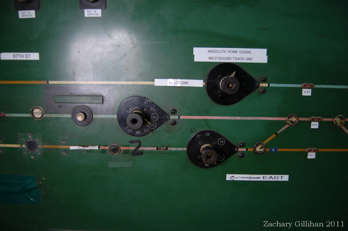
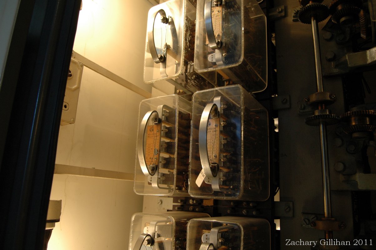
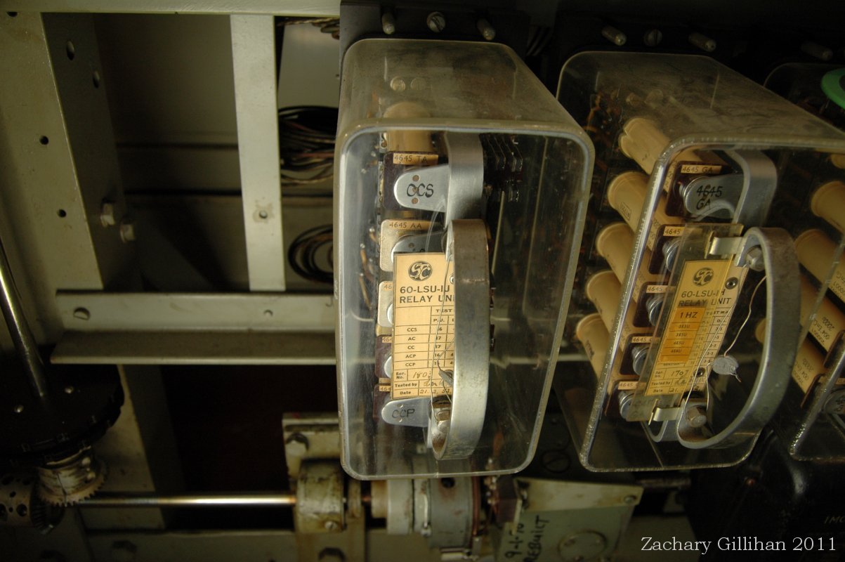
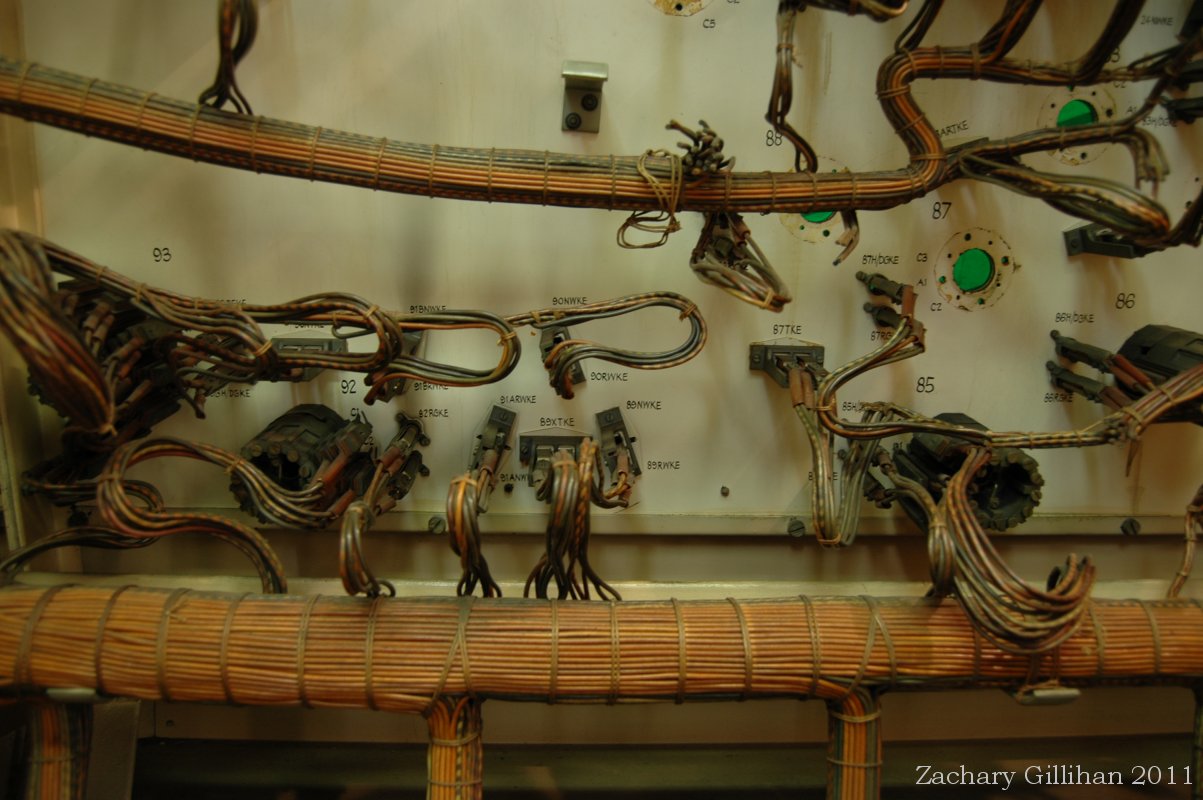
Both: Auxiliary Sequence Switch Relays, located to the left of the Sequence Switches.
The detection of all switch points, and the on or off indications of all signals, are repeated on the Panel, so that the Towerman is enabled to check that he has in fact set up the route he intended.
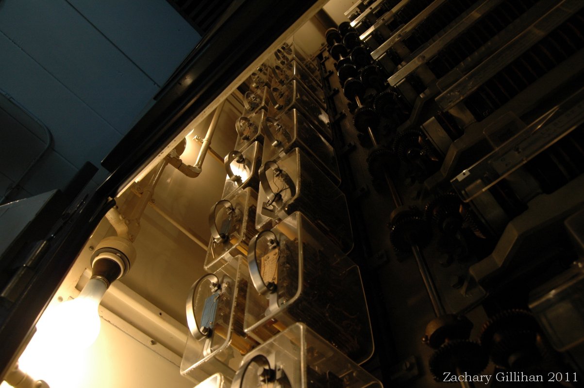
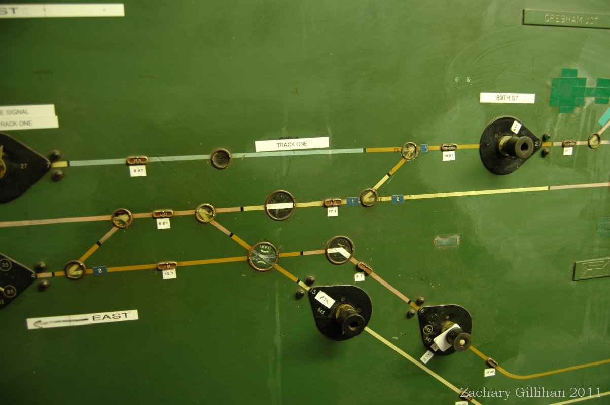
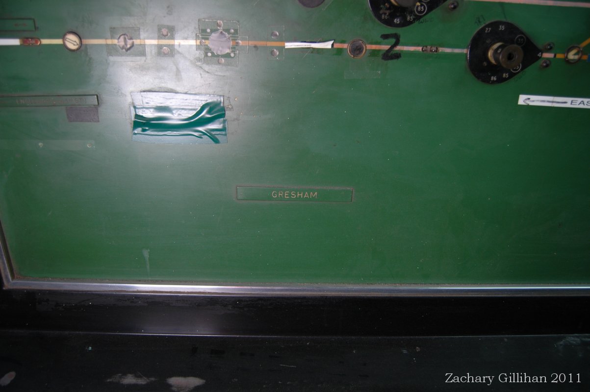
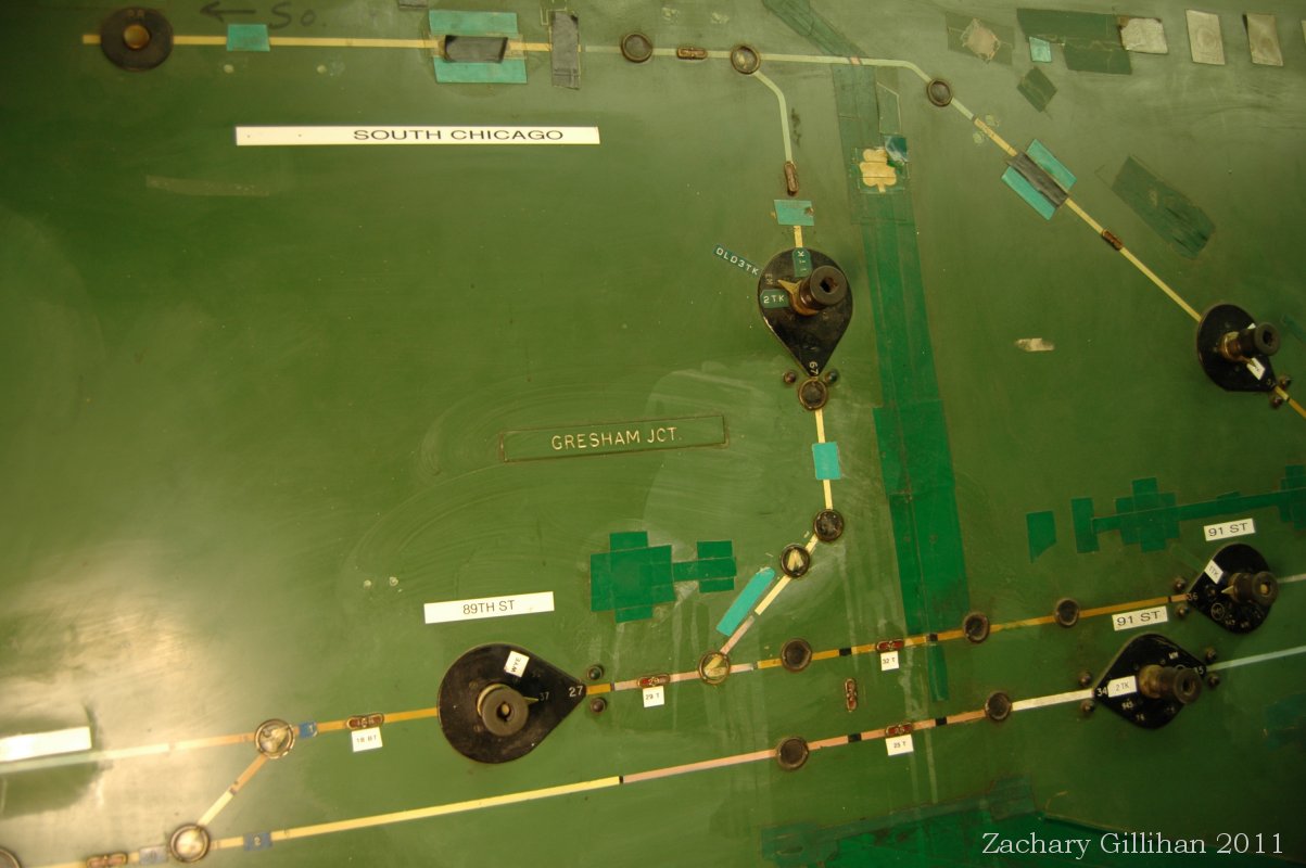
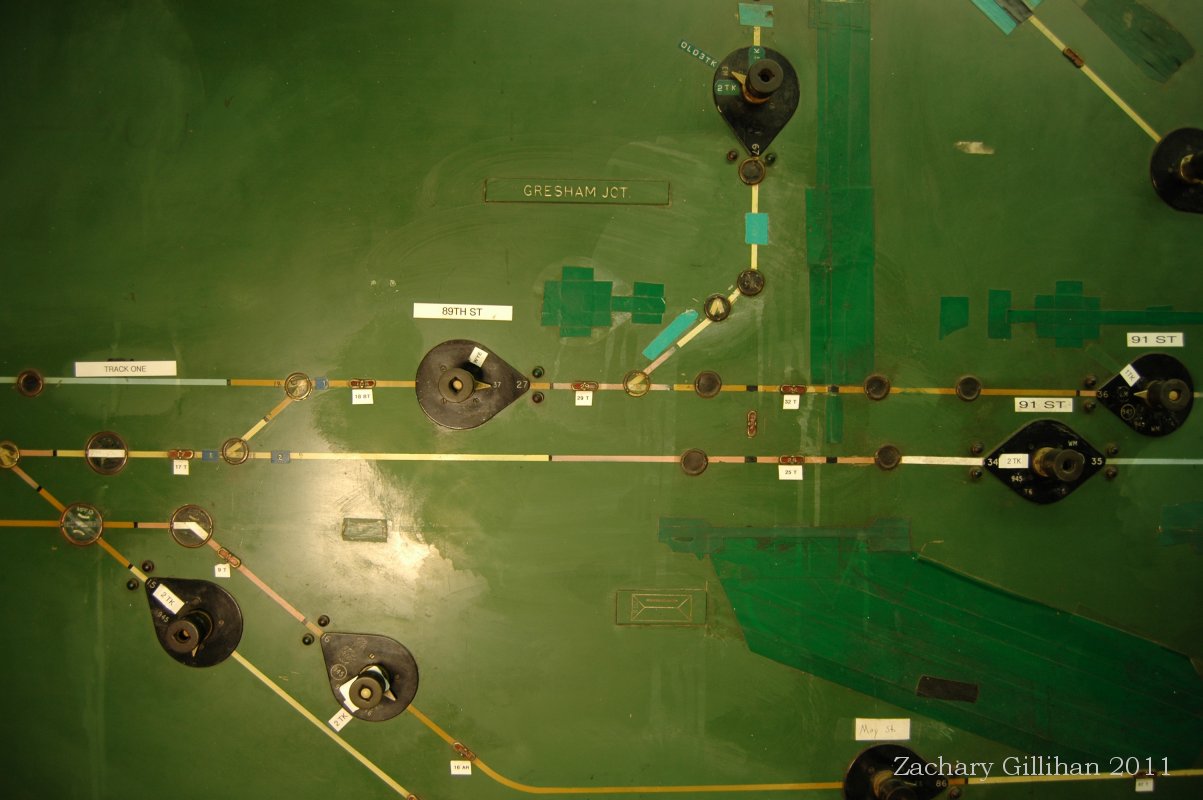
Both: Track Indicators and Switch Point Indicators on the Panel
After the train has passed through the route, and the Towerman wishes to restore the route to normal, he withdraws the plunger of the Route Selection Key, Whereupon the sequence switches associated with this particular route will restore to their Home positions, subject to Route Holding requirements.

In the case of routes which permit a train to travel out of the plant against the normal direction of traffic, the Towerman is required to operate a reverse route release key in addition to the usual route selection key.

At the top of the Control Panel are mounted the individual switch point control keys, which are of the 3-position type. Normally they would lie in the centre or 'C' position, and whilst in this position the switch points are controlled by the route selection equipment. If it is desired to operate a switch point independently of a route, or for the purpose of maintenance, then the switch point can be 'Normalled', or 'Reversed', by moving the appropriate individual switch point control key to the N or R position. These individual switch point keys are interlocked with the route control circuits in such a way that if a particular switch point is set by its individual key to the normal position, it is locked against any attempt to set up a route requiring it in a reverse position. Conversely, if a route has been established from a Route Selection Key which sets switch points into the reverse position, then the movement of the individual switch point control key to the normal position, will have no effect.
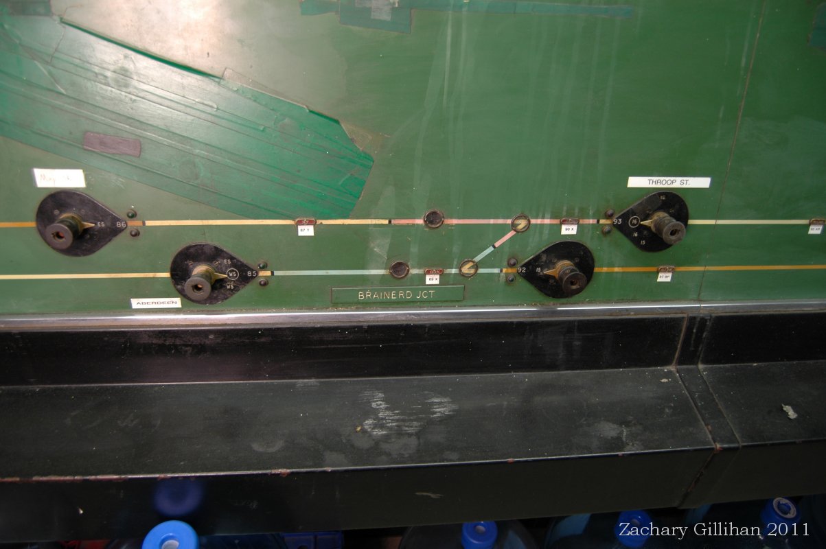
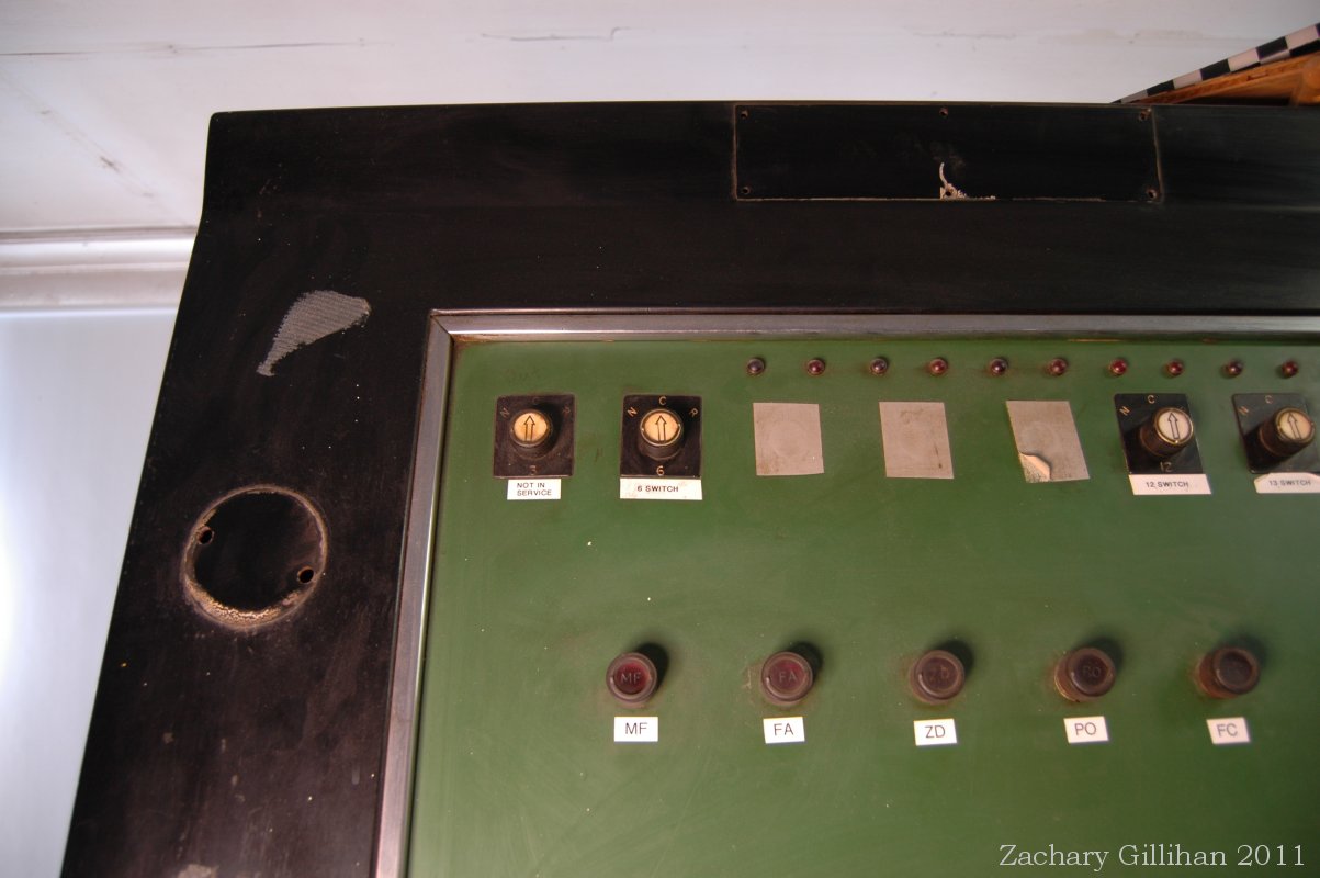
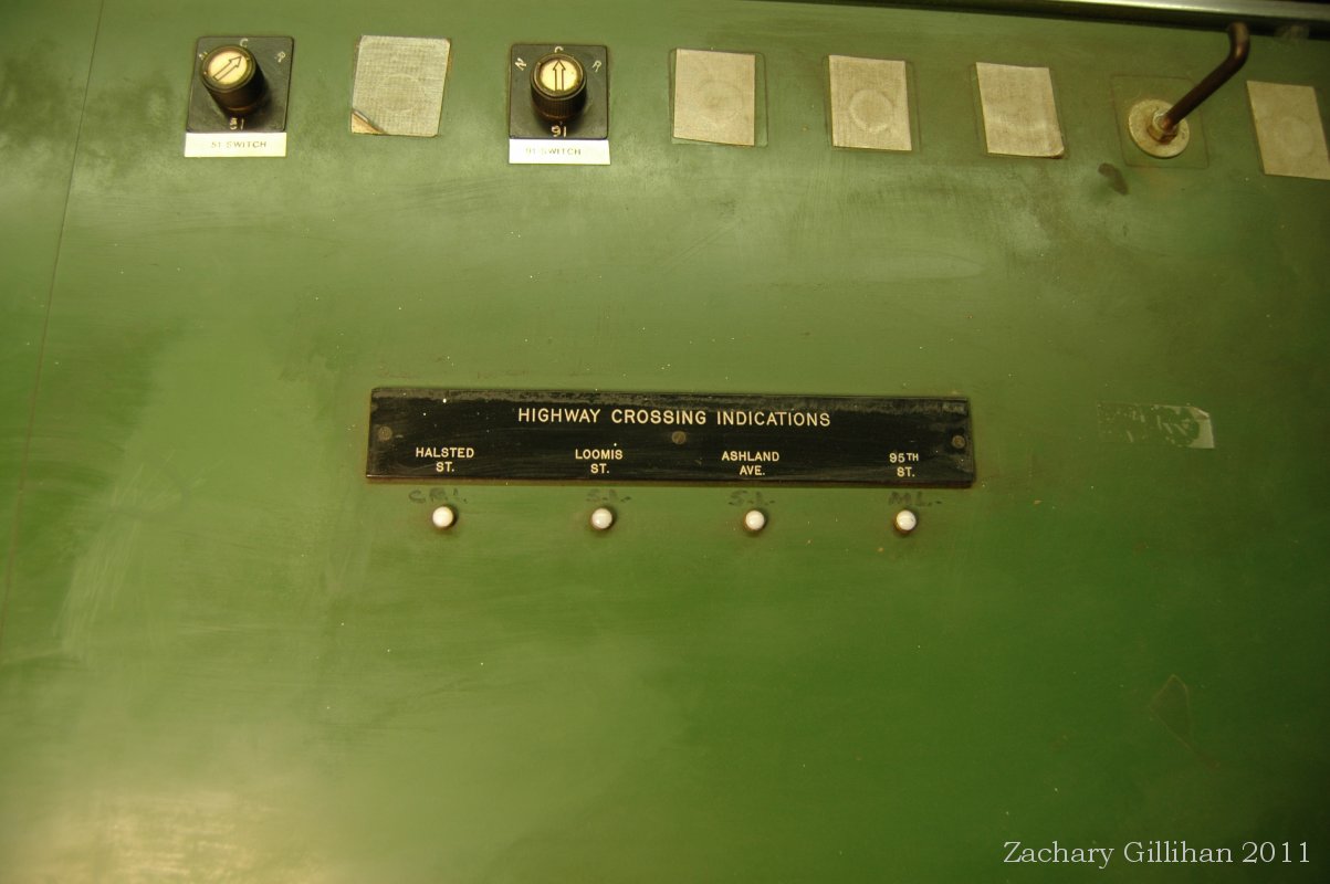
Both: Switch Point Control Keys at the top of the Panel.
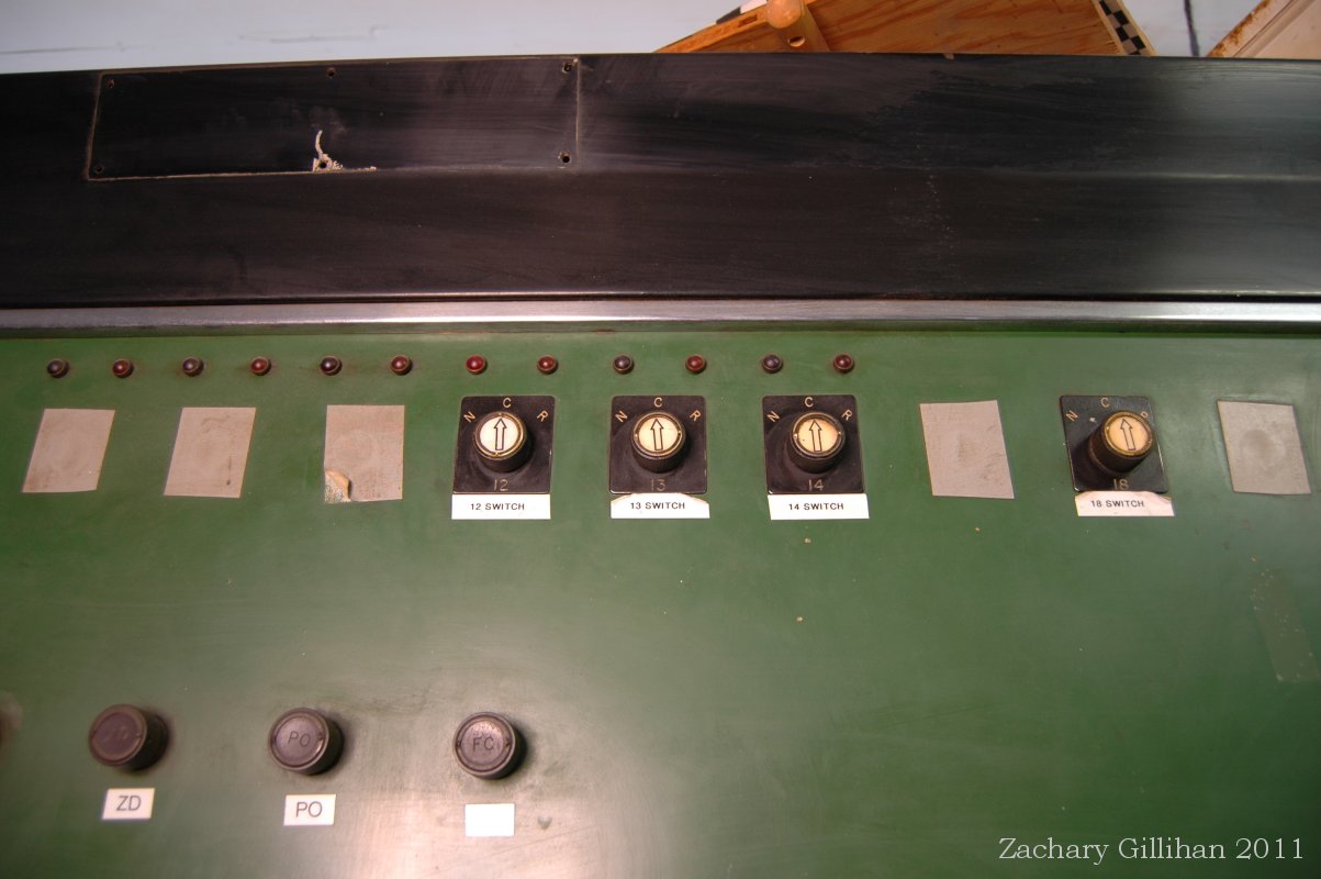
The tower prints were also not the tradional type of prints. They had special symbols for the contacts on the sequence switches and cams. The photos below are examples of the prints used at Gresham.


More Photos of the inside and outside of the tower: