|
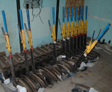
There are 2 types of lever beds that were widely used by railroads, they were the Improved Saxby and Farmer machine and the Style "A" Machine. We will focus on the Improved Saxby and Farmer Mechanical machine which is pictured to the left. The Improved Saxby and Farmer Machines levers were 5' 10 1/8" long and extended 4' above the floor. They were spaced 5" centers and came in 4 and 8 lever sections. The machine pictured to the left is two sections of 8 levers for a total of 16 levers. If the lever was away from the operator it was in the Normal position as if the lever was pulled towards the operator it was in the reversed position. Each lever had a number plate that was numbered from left to right. |
Track Model Board and Track Manipulation Chart
|
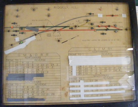
Every interlocking had a track model board showing the layout of the interlocking. They ranged widely depending on the maker and the railroads. Some were as simple as lines painted on a board as others were made from metal. AC Tower in Marion Ohio has the neatest model board I personally have ever seen. The model board on the left is a simple paper model board. Towers also had track manipulation charts which gave the proper lever arrangements for a route. These were extremely helpful for levermen that were not used to a tower, most levermen that had worked at a tower for sometime knew the lever arrangements by heart. Sometimes these boards were two different boards. The photo on the left is from UPRR Ridgley Tower, the track model board is combined with the track manipulation chart. |
Locking Beds
|
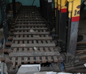
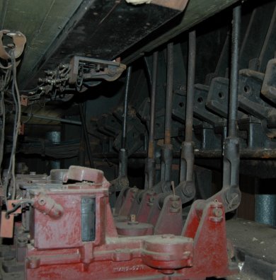
The locking beds on a Improved Saxby and Farmer machine were behind the levers. The locking bed was comprised of Longitudinal Locking Bars and locking dogs. These bars were connected to the levers and had locking dogs on them. The locking dogs (see next photo) were of all different sizes. When the levermen operated the lever it moved the rods and would move the locking dogs. Moving a lever may have moved a locking dog to stop you from being able to move another lever but allow you to move a different lever. This was known as mechanical locking. For much more information on this see the AAR Chapter XVI (INTERLOCKING) |
Locking Dogs
|
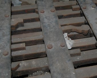
As mentioned above locking dogs were attached to the Longitudinal Locking Bars. These varied in size and shapes. The locking dogs are shown to the left, they are the raised metal parts. For much more information on this see the AAR Chapter XVI (INTERLOCKING) |
Forced Drop Electric Locks
|
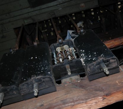
Forced Electric Locks are applied to electric locks to insure that the locking device is actuated to the locked position. These locks are locked when the magnets are de-energized. This lock is applied to the Improved Saxby and Farmer machine and is located under the floor. These are actuated by stepping on a button located on the floor in front of the lever they lock. Notice in the photo there are wires above the locks, these are the floor push buttons. These forced locks can also have rotary circuit controllers but are limited to the space under the floor. |
Circuit Controllers
|
Besides having optional circuit controllers on the electric locks, there may be circuit controllers added to the machine. We will focus on the Slide type circuit controllers like the ones pictured to the left. These could be connected to the lever, rod, rocking shaft, or the latch. They were used to check the position of the lever. The ones to the left were added to the signal levers when the interlocking was changed from a mechanical interlocking to a electro-mechanical interlocking. The slide type came in 4, 8, or 10 contact units, you could attach multiple slide controllers together for more contacts, all depended on the amount of room under the floor. |
Lever to Pipe Connections
|
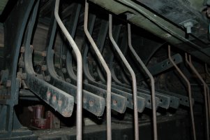
These are the lever tails, normally there would be pipes connected to the back of these. This interlocking was converted from mechanical pipes to electrical in 1954 and the pipe line was removed. After the pipe was connected here it went to the "leadout" which ranged from vertical cranks to rocker shafts. The difference between the use of vertical cranks to rocker shafts was in which way the pipe line needed to leave the tower. For example Shattuc tower had the lever bed and operator facing South, the vertical cranks made the pipe line exit the south wall of the tower. The rocker shafts allowed the pipe line to either exit from the east or west wall of the tower. See below for the vertical cranks and rocker shafts. |
A.A.R. defines a Leadout as "A term applied to the mechanical connections of an interlocking between the machine and outside pipe lines."
Rocker Shaft Leadouts
|
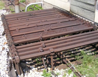
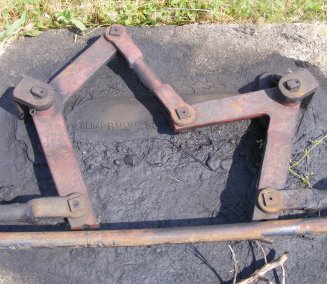
Rocker Shafts are made from a 2"x2" square metal bar that is of length required. It is supported by bearings spaced horizontally and not more than 6 feet part. The end of the rocker shaft that is inside the tower has a offset arm at the end of it to connect to the pipe from the lever. The photo on the left shows the outside part of the leadout, notice the offset arms on each bar. They are spaced in conjunction with the pipe line. For complex leadouts some offset arms are used with offset pipe line connections to provide clearance and spacing for other pipes. |
A.A.R. defines a Crank as "A lever, the arms of which form a angle, with the fulcrum at the vertex of the angle, which is used to transmit motion from one part of a line to another part."
Vertical Cranks
|
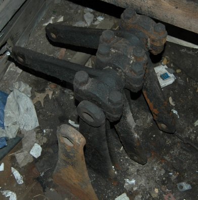
Vertical Cranks are used to connect the pipes from the levers to the horizontal cranks outside. When the lever was thrown in reverse it pulled the crank up which in turn pulled the pipe back towards the tower. When the lever was thrown from reverse to normal the crank was pushed down which in turn pushed the pipe away from the tower. In sort, vertical cranks took vertical motion and changed it to horizontal motion. |
Horizontal Cranks
|
Horizontal cranks are used to change the direction of the pipe line motion. If you pull the lever it pulls the pipe line and pulls the crank, the crank then pulls the other section of pipe line. There are several other types of cranks, we will focus on the Right-Angle Crank which is most common and pictured to the left. |
A.A.R. defines a Compensator as "a device for counteracting the expansion and contraction caused by changes of temperature in a pipe line, thereby maintaining a constant length of line between units."
Compensators
|
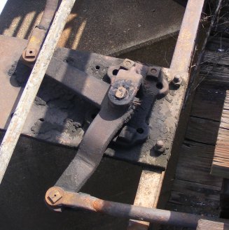
Pipe lines are subject to expansion and contraction from temperature, a compensator is installed between the leadout and the unit. The compensator pictured to the left is a one-way horizontal pipe compensator. It is made from a 60-degree and a 120-degree angle crank. Unlike the 90-degree crank that if the pipe pushes then the crank pushes, compensators are opposite. If a pipe motion is pushed into the compensator the pipe motion is pulled on the other side. Compensators can be also used to change the motion of a pipe line. |
A.A.R. defines a Pipe Carrier as "a device used to support, guide and facilitate the longitudinal movement of a pipe line."
Pipe Carriers
|
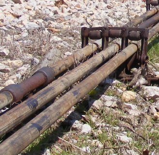
Pipe Carriers are basically rollers. The pipe line rides on the roller and there is a small roller that keeps the pipe line from rising out of the carrier. A one-way carrier is made of three parts, there are two frames and a roller. The frames have groves in the sides of them that the roller fits into. Once you have a one-way carrier if you want to make it a two-way all you do is add another roller and frame. These were vital to the pipe line and required lots of grease to keep them running smoothly. In the photo to the left you can tell the pipe lines in service and the ones not in service. |
Pipe Lines
|
The pipe line is made from 1 inch galvanized steel or wrought iron pipe. The pipe line is jointed together with a special 2 1/4 inch threaded coupling and a steel plug. The coupling is then riveted together. |
A.A.R. defines a Facing Point Lock as "a mechanical lock for a switch, derail or movable point frog, comprising a plunger stand and a plunger which engages a lock rod attached to the switch point to lock the operated unit."
Plunger Locks
|
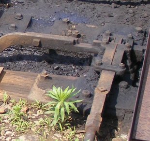
A lock is used to insure that a switch point is properly secured against the rails. The lock requires two levers, one to operate the lock and the other to operate the switch. There are two general types of plunger locks, one is a 1 inch circular and the other is a 2 inch by 3/4 inch rectangular. The lock in the photo to the left is the 2 inch by 3/4 inch rectangular lock. |
Switches
|
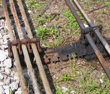
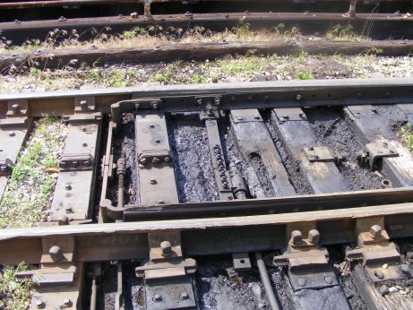
The photo on the left is a mechanical switch, this requires two levers to operate. One lever for the lock and the other is for the switch. These needed to be well maintained and greased otherwise it was quite hard to throw the lever. Snow and ice were a levermens worst nightmare. |
Dwarf Signals
|
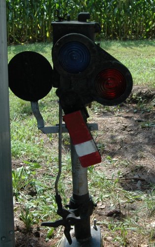
Dwarf signals were common along the tracks of mechanical interlockings. They ranged from 2 to 3 aspects and size. The one pictured on the left is a 2 aspect dwarf signal made by Union Switch and Signal Company. It is complete even with the phankil to stop false aspects. This dwarf was Stop or restricting. |
Signals
|
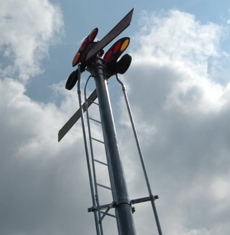
Signals were also controlled by the pipe line, they had cranks located at the base to connect the horizontal pipe to the vertical pipe. Signals were of semaphore type and the pipe line connected to the spectacle. Signals require one lever for each working arm, signal were normally equipped with counterweights to return the arm to normal in the event of the pipe line becoming broken or damaged. The photo on the left is a train order signal which is mechanical, you can see the pipe line and the pipe line supports. Train order signals were also controlled from the lever bed. |
Written By: Zachary Gillihan 2009